
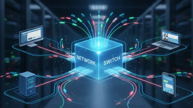
In computer networking, Switching is the foundational mechanism that enables data transmission across complex, interconnected networks without requiring dedicated physical connections between every pair of nodes. Without switching, global communication infrastructures—from enterprise LANs to the global Internet—would require an mathematically impossible mesh of physical cabling.
A switch is a high-speed networking device or logical process operating primarily at the Data Link Layer (Layer 2) or Network Layer (Layer 3) of the OSI model. Its core responsibility is to receive incoming data units, process addressing metadata, dynamically select an optimal outgoing path, and forward the data toward its ultimate destination with minimal latency, jitter, and packet loss.
This comprehensive, E-E-A-T-aligned guide delivers an end-to-end breakdown of switching paradigms in computer networks. We will analyze the core taxonomy of switching techniques, compare Circuit Switching and Packet Switching, explore Message Switching and Virtual Circuits, break down Layer 2 hardware switching mechanics (MAC learning, VLANs, Spanning Tree), and evaluate modern Software-Defined Networking (SDN) paradigms.
Core Takeaway: Switching transforms physical communication channels into efficient, dynamic data conduits. Modern digital communications rely predominantly on Packet Switching due to its high bandwidth utilization, statistical multiplexing, and resilience, whereas legacy systems and deterministic real-time channels utilized Circuit Switching.
1. Taxonomy of Switching Techniques
Switching methodologies are classified into three primary categories based on how physical resources (bandwidth, buffers, channels) are allocated during data transfer:
- Circuit Switching: Establishes a dedicated, physical end-to-end connection before data transfer begins (e.g., traditional PSTN landline telephony).
- Message Switching: A store-and-forward mechanism where entire messages are transmitted from node to node without size limits (e.g., historical telegraph networks, early email systems).
- Packet Switching: Breaks large messages into smaller, bounded units called packets, which are individually routed across shared network paths (e.g., the Internet, IP networks).
2. Deep Dive: Circuit Switching Mechanics
In a Circuit-Switched Network, a dedicated, continuous physical pathway (circuit) is established between the sender and receiver for the entire duration of the communication session. Channel resources—such as frequency bands, time slots, or wire pairs—are strictly reserved and unavailable to other network users, even when no data is actively being transmitted.
The 3 Operational Phases of Circuit Switching
- 1. Circuit Establishment: Before any data transfer occurs, a request signal travels from source to destination via intermediate switches. If all intermediate links have available capacity, a dedicated end-to-end path is locked, and an acknowledgment returns to the sender.
- 2. Data Transfer: Analog or digital data streams continuously through the reserved path. Because path resources are pre-allocated, data experiences constant latency and zero congestion queuing delay during transmission.
- 3. Circuit Teardown: When communication concludes, a tear-down signal releases the reserved links, releasing switches and transmission media for other communication sessions.
Multiplexing in Circuit Switching
To prevent needing a unique physical wire for every connection, circuit-switched networks partition physical trunks using multiplexing protocols:
- Frequency-Division Multiplexing (FDM): The link bandwidth is divided into distinct frequency channels (e.g., analog radio broadcasting).
- Time-Division Multiplexing (TDM): Transmission time is divided into recurring fixed-duration time slots allocated to specific sessions (e.g., T1/E1 digital carrier lines).
Advantages & Disadvantages of Circuit Switching
- Pros: Guaranteed bandwidth, deterministic transmission latency, zero packet reordering required.
- Cons: Extremely low resource efficiency during silent periods (bursty data leads to idle channel wastage), high connection setup overhead, lack of scalability for computer data traffic.
3. Deep Dive: Packet Switching Mechanics
Computer data traffic is inherently “bursty”—short bursts of intensive transmission followed by variable periods of inactivity. Packet Switching was developed to address the inefficiencies of circuit switching by eliminating dedicated end-to-end paths.
In packet switching, source hosts slice large application messages into smaller payload blocks called packets (typically 1,500 bytes for standard Ethernet MTU). Each packet is augmented with a control header containing source IP, destination IP, sequence numbers, and error-checking checksums.
Datagram Approach vs. Virtual Circuit Approach
Packet-switched networks operate under two distinct operational modes:
A. Connectionless Datagram Packet Switching (e.g., Standard IP)
Each packet is treated as an independent entity called a datagram. Intermediate routers inspect each packet’s destination IP independently and query local routing tables to determine the next hop.
- Packets belonging to the exact same message may travel along entirely different physical paths due to changing network topology or link congestion.
- Packets may arrive out-of-order, requiring transport layer protocols (like TCP) to resequence them at the receiver end.
- Highly fault-tolerant: If an intermediate link fails, subsequent datagrams automatically reroute around the failure point.
B. Connection-Oriented Virtual Circuit Packet Switching (e.g., ATM, Frame Relay, MPLS)
A hybrid approach combining aspects of circuit and packet switching. A logical pre-planned route called a Virtual Circuit (VC) is established between source and destination before data transmission begins.
- Packets do not require full global IP destination headers; instead, they carry short Virtual Circuit Identifiers (VCIs) or MPLS labels.
- All packets follow the exact same logical path, ensuring in-order delivery and predictable latency.
- Unlike pure circuit switching, physical link bandwidth is not strictly reserved; statistical multiplexing remains active.
4. Comprehensive Comparison: Circuit vs. Packet vs. Message Switching
| Comparison Dimension | Circuit Switching | Datagram Packet Switching | Virtual Circuit Packet Switching |
|---|---|---|---|
| Call Setup Required? | Yes, mandatory before data transfer. | No setup phase; immediate transfer. | Yes, virtual connection setup required. |
| Dedicated Physical Path? | Yes, strict continuous path. | No, dynamic independent paths. | No, shared logical path. |
| Resource Allocation | Pre-allocated / Reserved. | Dynamic / Demand-based. | Dynamic / Demand-based. |
| Bandwidth Efficiency | Low (idle times waste links). | High (Statistical Multiplexing). | High (Statistical Multiplexing). |
| Store-and-Forward Delay | None. | Yes, per-hop queuing delay. | Yes, per-hop queuing delay. |
| Link Failure Resilience | Poor (call drops if link breaks). | Excellent (auto-rerouting per packet). | Moderate (requires logical VC re-route). |
5. Layer 2 Hardware Switching: Ethernet & Switch Internal Mechanics
In Local Area Networks (LANs), hardware switches connect network endpoints (servers, PCs, IoT devices) using Ethernet protocols operating at Layer 2 (Data Link Layer). Understanding how a physical Ethernet switch operates internally is critical for network engineering.
A. The MAC Address Table (CAM Table) & Self-Learning Algorithm
Unlike legacy network hubs that blindly broadcast incoming electrical signals to all ports, a Layer 2 switch makes intelligent forwarding decisions using a Content-Addressable Memory (CAM) table containing [MAC Address | Switch Port | VLAN ID | Aging Timer] tuples.
The switch populates its CAM table dynamically using the MAC Self-Learning Algorithm:
- Ingress Frame Inspection: When an Ethernet frame arrives on Port 1, the switch inspects its Source MAC address.
- Learning Phase: The switch maps the Source MAC address to Port 1 in its CAM table and resets the aging timer for that entry.
- Forwarding Decision (Egress Lookup): The switch inspects the frame’s Destination MAC address:
- Known Unicast: If Destination MAC exists in CAM table (e.g., mapped to Port 3), the frame is forwarded solely to Port 3.
- Unknown Unicast / Broadcast: If Destination MAC is missing or is
FF:FF:FF:FF:FF:FF, the switch floods the frame out of all active ports except the ingress port (Port 1).
B. Switch Forwarding Modes
Internal hardware Application-Specific Integrated Circuits (ASICs) forward frames across backplane fabrics using one of three primary internal modes:
- Store-and-Forward: The switch buffers the entire Ethernet frame, verifies the Cyclic Redundancy Check (CRC) error checksum, and forwards it if error-free. Highly reliable, but introduces latency proportional to frame length.
- Cut-Through: The switch reads only the first 6 bytes of the frame (Destination MAC) and begins immediately outputting bits to the destination port before the frame has fully arrived. Lowest latency, but forwards corrupted frames containing CRC errors.
- Fragment-Free (Modified Cut-Through): The switch buffers the first 64 bytes of the frame (where most Ethernet collisions and corruptions occur) before forwarding. Balances speed with baseline collision filtering.
C. Virtual LANs (VLANs) & Trunking (IEEE 802.1Q)
By default, a physical Layer 2 switch represents a single broad Broadcast Domain. Uncontrolled broadcast traffic (ARP requests, DHCP discoveries) can degrade network performance.
Virtual Local Area Networks (VLANs) logically partition a single physical switch into multiple isolated broadcast domains. Traffic between different VLANs cannot pass at Layer 2 and requires a Layer 3 device (router or Layer 3 switch) to perform inter-VLAN routing. When traffic moves between switches across a shared link, the IEEE 802.1Q protocol inserts a 4-byte VLAN tag into the Ethernet header to preserve VLAN identity across trunk links.
D. Loop Prevention: Spanning Tree Protocol (STP / IEEE 802.1D)
To prevent single points of failure, enterprise networks deploy redundant physical links between switches. However, redundant Layer 2 links create physical loops. Because Layer 2 Ethernet headers lack a Time-To-Live (TTL) field, broadcast frames loop indefinitely, creating a catastrophic Broadcast Storm that consumes switch CPU and crashes the network.
The Spanning Tree Protocol (STP) prevents Layer 2 loops by dynamically discovering network topology and logically blocking redundant ports:
- Switches exchange Bridge Protocol Data Units (BPDUs) to elect a single Root Bridge (switch with lowest Bridge ID).
- Each non-root switch calculates its lowest-cost path back to the Root Bridge and assigns a Root Port.
- Redundant links forming loops are placed into a Blocking State (blocking data frames while continuing to process management BPDUs). If an active link fails, STP unblocks the redundant path to restore connectivity.
6. Layer 3 Switching, Multilayer Switching, and Routing
While traditional switches operate purely at Layer 2 using MAC addresses, modern enterprise networks deploy Layer 3 Switches (Multilayer Switches).
Layer 2 Switch vs. Layer 3 Switch vs. Traditional Router:
- Layer 2 Switch: Forwards Ethernet frames within a single subnet based on MAC addresses using ASICs. Cannot perform routing across subnets.
- Layer 3 Switch: Combines high-speed Layer 2 hardware switching with Layer 3 IP routing capabilities. Utilizes specialized TCAM (Ternary Content Addressable Memory) hardware tables to forward IP packets between VLANs at line rate (gigabit/terabit wire speeds).
- Traditional Router: Software-driven or modular Layer 3 device specializing in WAN connectivity, complex routing protocols (BGP, OSPF), NAT, deep security inspect, and wide-area interface encapsulation (HDLC, PPP).
7. Modern Trends: Software-Defined Networking (SDN) & OpenFlow
Traditional hardware switches integrate two distinct operational planes within a single physical chassis:
- Control Plane: Software intelligence that builds routing tables, calculates STP trees, and manages network policy.
- Data Plane (Forwarding Plane): Hardware ASICs that physically move packets from ingress ports to egress ports based on control plane rules.
Software-Defined Networking (SDN) decouples the control plane from physical switches, centralizing management intelligence into a software-based SDN Controller (such as OpenDaylight or ONOS). Physical switches become simple “white-box” data plane forwarders programmed dynamically via standardized Southbound APIs like OpenFlow or P4.
SDN allows hyper-scale data centers (AWS, Google, Azure) to dynamically provision virtual network switches, enforce micro-segmentation security, and optimize traffic engineering flows programmatically without touching individual switch CLIs.
Frequently Asked Questions (FAQs)
Internet traffic is naturally bursty with intermittent pauses. Packet switching utilizes statistical multiplexing, allowing multiple users to share the exact same link capacity dynamically. This provides orders of magnitude higher bandwidth efficiency and fault tolerance compared to reserving static physical links.
A Collision Domain is a network segment where simultaneous frame transmissions cause electrical signal interference (each port on a Layer 2 switch is an isolated collision domain). A Broadcast Domain is a logical segment where a broadcast frame is received by all connected hosts (all ports on an unconfigured switch share one broadcast domain, which can be subdivided using VLANs or routers).
If a switch CAM table reaches memory capacity (or is targeted by a malicious MAC Flooding Attack), the switch cannot store new MAC mappings. To maintain connectivity, it falls back to operating like a hub—flooding all incoming unicast frames out of every port, exposing traffic to packet sniffing.
Multiprotocol Label Switching (MPLS) is a Virtual Circuit packet-switching mechanism operating between Layer 2 and Layer 3 (often called Layer 2.5). It prepends short numerical labels to packets, enabling routers to make ultra-fast forwarding decisions along pre-determined Label Switched Paths (LSPs) without performing full IP routing table lookups.
8. Conclusion
Switching is the backbone of modern computer communications. From historical circuit-switched phone networks to packet-switched global IP networks, switching technologies have continuously evolved to maximize link efficiency, minimize communication latency, and scale to billions of connected endpoints.
Mastering the core principles of packet switching, Layer 2 hardware operations, VLAN segmentation, Spanning Tree loop prevention, and Software-Defined Networking empowers network engineers to design resilient, enterprise-grade network architectures capable of meeting modern digital demands.


Leave a Reply